OM 402PWR


OM 402PWR
4 DIGIT AC VOLTMETER AND AMMETER / NETWORK ANALYSER
The OM 402 model series are 4 digit panel programmable instruments designed for maximum usefulness and user comfort while maintaining their fair price. Type OM 402PWR is a multifunction AC voltmeter and ammmeter with extended functions for further analysis of electricity network. It measures voltage, current, active power, frequency, and through calculation also reactive power, apparent power and cos fi. The instrument is based on a single-chip microcontroller and a true RMS converter, which ensure good accuracy, stability and easy operation of the instrument.
-
4 digit programmable projection
-
range: 0…1/2,5/5 A; 0…60/150/300 mV; 0…10/120/250/450 V
-
digital filters, tare, linearization
-
size of DIN 96 x 48 mm
-
power supply 10…30 V AC/DC or 80…250 V AC/DC
Options
-
comparators
-
data output
-
analog output
-
measured data record
-
three-color display - 20 mm
for amplitude from 8 V
Current (Irms)
Real power (P-W)
Frequency (Hz)
with calculation
-999…9999, 3-coloured 7-segment LED
| 1, 2, 3, 4 | Limits L1, L2, L3, L4 (red) |
| T | Tare (green) |
| M | Min./Max. value (green) |
| I, U, P, F | Channels current, voltage, power, frequency (orange) |
| Kan I | Value from channel I |
| Fil. I | Value from channel I after digital filter adjustment |
| Kan U | Value from channel U |
| Fil. U | Value from channel U after digital filter adjustment |
| Kan P | Value from channel P |
| Fil. P | Value from channel P after digital filter adjustment |
| Kan F | Value from channel F |
| Fil. F | Value from channel F after digital filter adjustment |
| COS 02 | Value from secondary channel "cos fi" |
| Mat. Fn. | Value of mathematical function |
| Max. | Maximum value |
| Min. | Minimum value |
Selected functions can also be controlled via external inputs
| LIGHT | contains only items necessary for basic device settings with password access |
| PROFI | Full device settings with password access |
| USER | User menu of any item, selected from LIGHT/PROFI. Access without password. |
| ZAKAZ | button has no function |
| NUL. M.M. | Resetting Min/Max vaslues |
| NUL. TA. | Tare reset |
| MENU | Direct access to the selected menu item |
| DOC. H. | Temporary projection of selected values |
| TARA | Activating function Tare |
| ULOZ | Starting recording of the measured data into device memory |
| NUL. PA. | Resetting memory of the measured data |
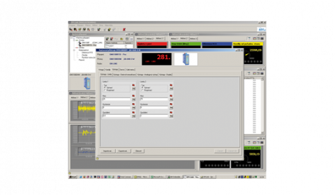
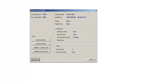
OM Link program is also designed for visualization and filing of meas. values from more instruments
(for projection 9999 and 5 measur./s)
| arithmetic mean | from 2…100 measurements |
| floating mean | from 2…30 measurements |
| exponential mean | from 2…100 measurements |
| rounding | setting projection step for display |
| Tare | designed to reset display on non-zero input signal |
| Min/max value | registration of min./max. value achieved during measurement |
| Peak value | display shows only max. or min. values |
| RTC | period - 1 s…1 day, time-date-display value, < 266k data, 15 ppm/°C |
| Hysteresis | switch. point, hysteresis band "Mez ± 1/2 Hys." and time (0 ... 99.9 s) determ. switching delay |
| From-To | output interval ON and OFF |
| Dose | period, its multiples and time (0 ... 99.9 s), during which the output is active |
2x relay, switch-over contact (250 VAC/30 VDC, 3 A)
1x relay, switch on contact (250 VAC/30 VDC, 3A)
2x relay, switch on contact (250 VAC/30 VDC, 3 A)
2x bistable relay (250 VAC/30 VDC, 3A)
3x relay, 2x switch on + 1x switch-over contact (250 VAC/30 VDC, 3A)
4x relay, 2x switch on + 2x switch-over contact (250 VAC/30 VDC, 3A)
2x open collector (30 VDC/100 mA)
4x open collector (30 VDC/100 mA)
2x open collector (30 VDC/100 mA) + 2x relay, CO contact (250 VAC/30 VDC, 3 A)
2x SSR (250 VAC/1 A)
error message indication (<3.0 mA)
Detection of current loop interruption
7 bits + even parity + 1 stop bit (Messbus)
0,0096…12 MBaud (PROFIBUS)
80…250 V AC/DC, ±10 %, PF > 0,4, I < 40 A/1 ms, isolated
4 kVAC within 1 min. between pow. supply and data/anal. output
4 kVAC within 1 min. between input and relay output
2,5 kVAC within 1 min.between input and data/anal. output
| power supply | 670 V (ZI), 300 V (Di)* |
| input, output, PN | 300 V (ZI), 150 V (Di)* |


Datasheets
| File name | File type | Version | Language | Download |
|---|---|---|---|---|
|
Datasheet OM402
Datasheet OM402
Datasheet OM402
Katalogový list OM402
|
PDF
|
2015.1 |
|
Download |
|
Datasheet OM402
Datasheet OM402
Datasheet OM402
Katalogový list OM402
|
PDF
|
2014.2 |
|
Download |
|
Datasheet OM402
Datasheet OM402
Datasheet OM402
Katalogový list OM402
|
PDF
|
2013.2 |
|
Download |
|
Datasheet OM402
Datasheet OM402
Datasheet OM402
Katalogový list OM402
|
PDF
|
2012.2 |
|
Download |
|
Datasheet OM402
Datasheet OM402
Datasheet OM402
Katalogový list OM402
|
PDF
|
2010.1 |
|
Download |
|
Datasheet OM402
Datasheet OM402
Katalogový list OM402
|
PDF
|
2008.1 |
|
Download |
|
Datasheet OM402
Katalogový list OM402
|
PDF
|
2006.2 |
|
Download |
|
Datasheet OM402PWR
Katalogový list OM402PWR
|
PDF
|
2023.1 |
|
Download |
|
Datasheet OM402PWR
Datasheet OM402PWR
Datasheet OM402PWR
Katalogový list OM402PWR
|
PDF
|
2020.1 |
|
Download |
| Katalogový list OM402 |
PDF
|
2009.1 | cs | Download |
| Katalogový list OM402 |
PDF
|
2007.1 | cs | Download |
User manuals
| File name | File type | Version | Language | Download |
|---|---|---|---|---|
|
Operating instructions OMProfi
Návod OMProfi
|
PDF
|
2020.3 |
|
Download |
|
Operating instructions OM402PWR
Návod OM402PWR
Operating instructions OM402PWR
|
PDF
|
2013.3.1 |
|
Download |
|
Operating instructions OMProfibus
Návod OMProfibus
|
PDF
|
2014.2.1 |
|
Download |
| Návod OMProfibus |
PDF
|
2014.2.0 | cs | Download |
| Návod OM402PWR_20 |
PDF
|
2007.1.0 | cs | Download |
|
Operating instructions OMProfibus
Návod OMProfibus
|
PDF
|
2010.1.2 |
|
Download |
| Návod OMProfibus |
PDF
|
2007.1.0 | cs | Download |
| Operating instructions OMProfibus |
PDF
|
2010.1.1 | en | Download |
Application notes
| File name | File type | Version | Language | Download |
|---|---|---|---|---|
|
Application note Handling RealTime memory
Aplikační list Obsluha pameti RealTima
|
PDF
|
2006.01 |
|
Download |
| Application note Upload firmware |
PDF
|
2014.02 | ru | Download |
|
Application note Firmware upload
Aplikační list Upload firmware
|
PDF
|
2006.02 |
|
Download |
|
Application note Modbus commands OM 402PWR
Aplikační list Modbus prikazy OM 402PWR
|
XLS
|
2019 |
|
Download |
|
Application note Modbus commands OM 402PWR-20
Aplikační list Modbus prikazy OM 402PWR20
|
XLS
|
2016 |
|
Download |
| Application note Protocol MODBUS description |
PDF
|
2006.01 | en | Download |
| Aplikační list protokol MODBUS popis |
PDF
|
2021.01 | cs | Download |
Certificates
| File name | File type | Version | Language | Download |
|---|---|---|---|---|
|
Certificate Declaration_17050_OM402
Certifikát Prohlaseni_17050_OM402
|
PDF
|
2022 |
|
Download |
|
Certificate Seismic_test_OM402UNI
Certifikát Seizmicka_zkouska_OM402UNI
|
PDF
|
2007 |
|
Download |
|
Certificate EU_Declaration_OM402
Certifikát EU_Prohlášení_OM402
|
PDF
|
2024 |
|
Download |
Firmware
| File name | File type | Version | Language | Download |
|---|---|---|---|---|
| OM 402PWR 78-604 |
HEX
|
2018 | xx | Download |
Software
| File name | File type | Version | Language | Download |
|---|---|---|---|---|
|
GSD OM-Profibus
GSD OM-Profibus
|
ZIP
|
2020 |
|
Download |
| GSDML OM-Profinet |
ZIP
|
2020.2.33 | xx | Download |
| GSDML OM-Profinet |
ZIP
|
2024.2.33 | xx | Download |
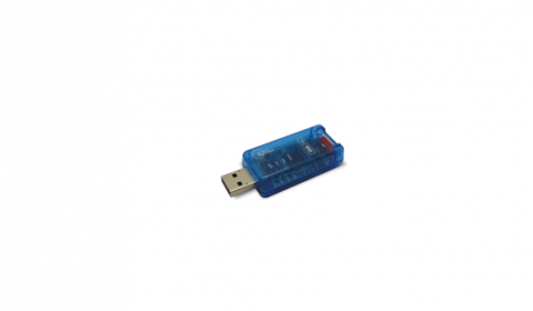
ISOLATED TRANSDUCER • USB < > OM INSTRUMENTS
Small compact transducer OM LINK USB with cable ensures safe and comfortable galvanically isolated connection between your computer and ORBIT MERRET instruments.