


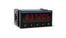
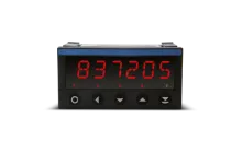
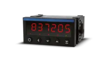
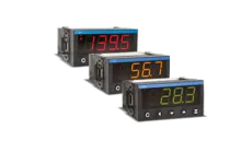
OM 602UQC
6 digit DUAL UNIVERSAL COUNTER
Type OM 602UQC is a universal programmable dual panel counter/frequency meter/evaluation of signals from IRC sensors, and clock/timer. The instrument is based on a single-chip microcontroller and an efficient gate array, which ensure good accuracy, stability and easy operation of the instrument.
-
6 digit programmable projection
-
counter/frequencymeter/clock/timer
-
0,002 Hz…1 MHz; UP/DW; IRC
-
tare/preset/sum/math.funkctions
-
digital filters, input filters
-
size of DIN 96 x 48 mm
-
power supply 10…30 V AC/DC or 80…250 V AC/DC
Options
-
excitation
-
comparators
-
data output
-
analog output
-
measured value record
Input
UQC
Input
2 independent inputs, menu selectable
on contact, TTL, NPN/PNP, Line
0...60 V, comparation levels are adjustable in the menu
on contact, TTL, NPN/PNP, Line
0...60 V, comparation levels are adjustable in the menu
Input frequency
0,002 Hz…1 MHz
0,002 Hz…100 kHz (Mode STRIDA)
0,002 Hz…500 kHz (Mode QUADR and UP/DW)
0,002 Hz…100 kHz (Mode STRIDA)
0,002 Hz…500 kHz (Mode QUADR and UP/DW)
Measurement mode
| SINGLE | Counter/Frequency |
| A + B | Counter/Frequency with AND function |
| xNOR | Counter/Frequency with NOR function |
| STRIDA | Duty cycle measurement |
| QUADR | Counter/Frequency for IRC sensor |
| UP/DW | Counter/Frequency |
| UP - DW | Counter/Frequency |
| TIME | Stopwatch |
| RTC | Clock |
Time base
0,05/1/2/3/5/10/20 s
1/2/5/10 min
1/2/5/10 min
Calibration coefficient
0,00001…999999
Preset
0…999999
Input filter
out
1/10/100/250/500/1 000 kHz
1/10/45/55/65/100 Hz
2/5/10 s
1/10 min
1/10/100/250/500/1 000 kHz
1/10/45/55/65/100 Hz
2/5/10 s
1/10 min
Functions
| Preset | initial non-zero value, which is always read after resetting the instrument |
| Current value | single setting of the initial value |
| Summation | registration of numbers during shift operation |
| Time backup | time is running even when the device is off (the display is off either) |
External inputs
Number
3 inputs, on contact
Functions
| OFF | No function |
| HOLD | Stopping measurement (option: Display - Analog output - Limits) |
| BLOK.K. | Blocking front panel keys |
| B.HESL. | Blocking access to the LIGHT/PROFI menu |
| TARA x | Tare activation - Channel 1, 2, All, Current |
| Suma x | Sum display - channel 1, 2 |
| N.SUM. x | Resetting sum - channel 1, 2, both |
| NUL. T.x | Resetting tare - 1, 2, All, Current |
| NUL. M.M. | Resetting Min/Max. value |
| ULOZ | Data record activation (extention of RTC/FAST) |
| PREP. | Gradual or BCD switching of the channels |
Projection
Display range
-99999…999999, single-coloured 14-segment LED
Display height
14 mm
Display colour
red, green
Signalizing LED
| T | Tare (green) |
| M | Min./Max. value (green) |
| C, F, 1, 2 | Channels 1, 2 - counter, frequency (orange) |
Description
the last two digits of the display can be used to display measured variables (only 14 mm display)
Decimal point
menu adjustable - fixed or floating
Display brightness
menu adjustable
Displayed values
| Kan C1 | Value from channel 1 - Counter |
| Fil. C1 | Value from channel 1 - Counter after digital filter adjustment |
| Kan F1 | Value from channel 1 - Frequency |
| Fil. F1 | Value from channel 1 - Frequency after digital filter adjustment |
| Kan C2 | Value from channel 2 - Counter |
| Fil. C2 | Value from channel 2 - Counter after digital filter adjustment |
| Fil. F2 | Value from channel 2 - Frequency after digital filter adjustment |
| Kan F2 | Value from channel 2 - Frequency |
| Mat. Fn. | Value of mathematical function |
| Max. | Maximum value |
| Min. | Minimum value |
Settings
Control
The device is controlled and set by five buttons on the front panel
Selected functions can also be controlled via external inputs
Selected functions can also be controlled via external inputs
Menu
| LIGHT | contains only items necessary for basic device settings with password access |
| PROFI | Full device settings with password access |
| USER | User menu of any item, selected from LIGHT/PROFI. Access without password. |
Optional functions
Buttons "Left", "Up", "Down", "Enter" can be assigned additional optional features
| ZAKAZ | button has no function |
| NUL. C.x. | Counter reset - channel 1, 2, both |
| N. SUM.x. | Summation reset - channel 1, 2, both |
| NUL. M.M. | Resetting Min/Max vaslues |
| NUL. T.x | Tare reset - Channel 1, 2, both, current |
| MENU | Direct access to the selected menu item |
| DOC. H. | Temporary projection of selected values |
| PREP. 1 | Switching channels on display |
| ULOZ | Starting recording of the measured data into device memory |
| NUL. PA. | Resetting memory of the measured data |
| START | Start for Stopwatch/watch |
| PAUZA | Till the next touch the display will show the last value |
| CLR | Resetting Stopwatch/Watch |
| STOP | Stopping Stopwatch/Watch |
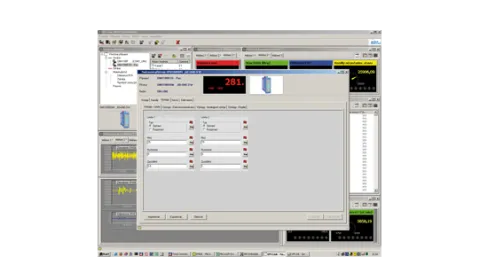
OM Link
Company communication interface for operation, setting and update of device firmware
OM Link program is also designed for visualization and filing of meas. values from more instruments
OM Link program is also designed for visualization and filing of meas. values from more instruments
Instrument accuracy and functionality
Temperature coefficient
50 ppm/°C
Accuracy
±0,01 % of range + 1 digit (frequency)
Overload capacity
2x; 10x (t < 30 ms)
Linearization
linear interpolation in 50 points (only via OM Link)
Digital filters
| arithmetic mean | from 2…100 measurements |
| floating mean | from 2…30 measurements |
| exponential mean | from 2…100 measurements |
| rounding | setting projection step for display |
| input filter | transmits input signal range 1 MHz...10 min |
Functions
| Tare | designed to reset display on non-zero input signal |
| Min/max value | registration of min./max. value achieved during measurement |
| Peak value | display shows only max. or min. values |
| Preset | initial non-zero value, which is read after each counter reset |
| Summation | number registration upon shift operation |
| Time backup | time is running even when the power is off (display is off either) |
| Current value | single setting of the initial value |
Math. functions
polynom, 1/x, logarithm, exponential, power, root, sin x
Math. operations between inputs
sum and quotient
Data record
Measured data recording into the memory
Not available in combination with with the data output MODBUS
| RTC | period - 1 s…1 day, time-date-display value, < 266k data, 15 ppm/°C |
| FAST | 40 records/s, display value, < 8k data |
Time backup
Lithium cell CR 2032RV, 3V/220 mAh
Watch-dog
reset after 400 ms
Calibration
at 25°C and 40 % r.h.
Comparators
Type
Digital, menu adjustable, contact connect. < 30 ms
Mode
| Hysteresis | switch. point, hysteresis band "Mez ± 1/2 Hys." and time (0 ... 99.9 s) determ. switching delay |
| From-To | output interval ON and OFF |
| Dose | period, its multiples and time (0 ... 99.9 s), during which the output is active |
| C-Pulse | auto counter reset on the preset value |
| On Run | output is active while stopwatch is running |
Output
1x relay, switch-over contact (250 VAC/30 VDC, 3 A)
2x relay, switch-over contact (250 VAC/30 VDC, 3 A)
1x relay, switch on contact (250 VAC/30 VDC, 3A)
2x relay, switch on contact (250 VAC/30 VDC, 3 A)
2x bistable relay (250 VAC/30 VDC, 3A)
3x relay, 2x switch on + 1x switch-over contact (250 VAC/30 VDC, 3A)
4x relay, 2x switch on + 2x switch-over contact (250 VAC/30 VDC, 3A)
2x open collector (30 VDC/100 mA)
4x open collector (30 VDC/100 mA)
2x open collector (30 VDC/100 mA) + 2x relay, CO contact (250 VAC/30 VDC, 3 A)
2x SSR (250 VAC/1 A)
2x relay, switch-over contact (250 VAC/30 VDC, 3 A)
1x relay, switch on contact (250 VAC/30 VDC, 3A)
2x relay, switch on contact (250 VAC/30 VDC, 3 A)
2x bistable relay (250 VAC/30 VDC, 3A)
3x relay, 2x switch on + 1x switch-over contact (250 VAC/30 VDC, 3A)
4x relay, 2x switch on + 2x switch-over contact (250 VAC/30 VDC, 3A)
2x open collector (30 VDC/100 mA)
4x open collector (30 VDC/100 mA)
2x open collector (30 VDC/100 mA) + 2x relay, CO contact (250 VAC/30 VDC, 3 A)
2x SSR (250 VAC/1 A)
Analogue outputs
Type
Isolated, programmable with a 16-bit D / A converter, type and range are menu selectable
Temperature coefficient
15 ppm/°C
Nonlinearity
±0,1 % of range
Rate
response to value change < 1 ms
Ranges
0...2 V, 0...5 V, 0...10 V, ±10 V, 0...5 mA, 0...20 mA, 4...20 mA
Compensation
600 Ohm/12 V, 1 000 Ohm/24 V
Error state
at range of 4...20mA
error message indication (<3.0 mA)
Detection of current loop interruption
error message indication (<3.0 mA)
Detection of current loop interruption
Data outputs
Protocol
ASCII, MESSBUS, MODBUS - RTU, PROFIBUS DP
Data format
8 bits + no parity + 1 stop bit (ASCII)
7 bits + even parity + 1 stop bit (Messbus)
7 bits + even parity + 1 stop bit (Messbus)
Rate
600…230 400 Baud
0,0096…12 MBaud (PROFIBUS)
0,0096…12 MBaud (PROFIBUS)
RS 232
isolated
RS 485
isolated, addressing max. 31 instruments
Sensor excitation
Adjustable
5…24 VDC/max. 1,2 W
Power supply
Power supply
10…30 V AC/DC, ±10 %, PF > 0,4, I < 40 A/1 ms, isolated
80…250 V AC/DC, ±10 %, PF > 0,4, I < 40 A/1 ms, isolated
80…250 V AC/DC, ±10 %, PF > 0,4, I < 40 A/1 ms, isolated
Current draw
< 8,0 W/7,8 VA
Power supply protection
Power supply is protected by a fuse inside the instrument
Mechanical properties
Dimensions
96 x 48 x 120 mm (w x h x d)
Panel cutout
90,5 x 45 mm (w x h)
Material
Noryl GFN2 SE1, non-inflammable UL 94 V-I
Operating conditions
Connection
connector terminal board, cable section < 1,5/2,5 mm2
Stabilization period
within 15 minutes after switch on
Operating temperature
-20°…60°C
Storage temperature
-20°…80°C
Protection class
IP64 (front panel only)
El. safety
EN 61010-1, A2
Dielectric strength
4 kVAC within 1 min. between pow. supply and input
4 kVAC within 1 min. between pow. supply and data/anal. output
4 kVAC within 1 min. between input and relay output
2,5 kVAC within 1 min.between input and data/anal. output
4 kVAC within 1 min. between pow. supply and data/anal. output
4 kVAC within 1 min. between input and relay output
2,5 kVAC within 1 min.between input and data/anal. output
Insulation resistance
for polution degree II, measuring cat. III.
| power supply | 670 V (ZI), 300 V (Di)* |
| input, output, PN | 300 V (ZI), 150 V (Di)* |
EMC
EN 61326-1
Seismic capacity
IEC 980: 1993, par.6
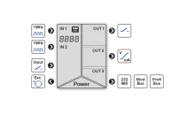
Images
Connection

Dimensions and installation

Datasheets
| File name | File type | Version | Language | Download |
|---|---|---|---|---|
|
ds01_OM602UQC_2023.1_en.pdf
ds01_OM602UQC_2023.1_cs.pdf
|
PDF
|
2023.1 |
|
Download |
|
ds01_OM602UQC_a2020.1_en.pdf
ds01_OM602UQC_a2020.1_fr.pdf
ds01_OM602UQC_a2020.1_ru.pdf
ds01_OM602UQC_a2020.1_cs.pdf
|
PDF
|
2020.1 |
|
Download |
User manuals
| File name | File type | Version | Language | Download |
|---|---|---|---|---|
|
man0100_OMProfi_2020.3_en.pdf
man0100_OMProfi_2020.3_cs.pdf
|
PDF
|
2020.3 |
|
Download |
|
man0101_OMProfibus_a2014.2.1_en.pdf
man0101_OMProfibus_a2014.2.1_cs.pdf
|
PDF
|
2014.2.1 |
|
Download |
| man0101_OMProfibus_a2014.2.0_cs.pdf |
PDF
|
2014.2.0 | cs | Download |
|
man0102_OMProfibus_a2010.1.2_en.pdf
man0102_OMProfibus_a2010.1.2_cs.pdf
|
PDF
|
2010.1.2 |
|
Download |
| man0102_OMProfibus_a2007.1.0_cs.pdf |
PDF
|
2007.1.0 | cs | Download |
| man0102_OMProfibus_a2010.1.1_en.pdf |
PDF
|
2010.1.1 | en | Download |
| man09_OM602UQC_2011.3.1_cs.pdf |
PDF
|
2011.3.1 | cs | Download |
|
man010_OM602UQC_2010.1.1_en.pdf
man010_OM602UQC_a2010.1.1_cs.pdf
|
PDF
|
2010.1.1 |
|
Download |
| man010_OM602UQC_a2010.1.0_cs.pdf |
PDF
|
2010.1.0 | cs | Download |
Application notes
| File name | File type | Version | Language | Download |
|---|---|---|---|---|
|
an01_Handling RealTime memory _2006.01_en.pdf
an01_Obsluha pameti RealTima_2006.01_cs.pdf
|
PDF
|
2006.01 |
|
Download |
|
an02_Firmware upload_2006.02_en.pdf
an02_Upload firmware_2006.02_cs.pdf
|
PDF
|
2006.02 |
|
Download |
| an02_Upload firmware_2014.02_ru.pdf |
PDF
|
2014.02 | ru | Download |
|
an05_Modbus commands OM 602UQC_2018_en.xls
an05_Modbus prikazy OM 602UQC_2018_cs.xls
|
XLS
|
2018 |
|
Download |
| an05_protokol MODBUS popis_2021.01_cs.pdf |
PDF
|
2021.01 | cs | Download |
| an05_Protocol MODBUS description_2006.01_en.pdf |
PDF
|
2006.01 | en | Download |
Certificates
| File name | File type | Version | Language | Download |
|---|---|---|---|---|
|
crt02_EU_Declaration_OM602_2022_en.pdf
crt02_EU_Prohlaseni_OM602_2022_cs.pdf
|
PDF
|
2022 |
|
Download |
|
crt03_Declaration_17050_OM602_2022_en.pdf
crt03_Prohlaseni_17050_OM602_2022_cs.pdf
|
PDF
|
2022 |
|
Download |
|
crt04_Seismic_test_OM602UQC_2007_en.pdf
crt04_Seizmicka_zkouzka_OM602UQC_2007_cs.pdf
|
PDF
|
2007 |
|
Download |
Firmware
| File name | File type | Version | Language | Download |
|---|---|---|---|---|
| sw01_OM 602UQC 78-601_2018_xx.hex |
HEX
|
2018 | xx | Download |
Software
| File name | File type | Version | Language | Download |
|---|---|---|---|---|
|
sw03_GSD OM-Profibus_2020_xx.zip
sw03_GSD OM-Profibus_2020_xx.zip
|
ZIP
|
2020 |
|
Download |
| sw04_GSDML OM-Profinet_2020.2.33_xx.zip |
ZIP
|
2020.2.33 | xx | Download |
| sw05_GSDML OM-Profinet_2024.2.33_xx.zip |
ZIP
|
2024.2.33 | xx | Download |
CAD
| File name | File type | Version | Language | Download |
|---|---|---|---|---|
| drw01_OM Krabicka_2014_xx.dwg |
DWG
|
2014 | xx | Download |
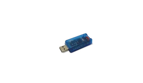
ISOLATED TRANSDUCER • USB < > OM INSTRUMENTS
Small compact transducer OM LINK USB with cable ensures safe and comfortable galvanically isolated connection between your computer and ORBIT MERRET instruments.